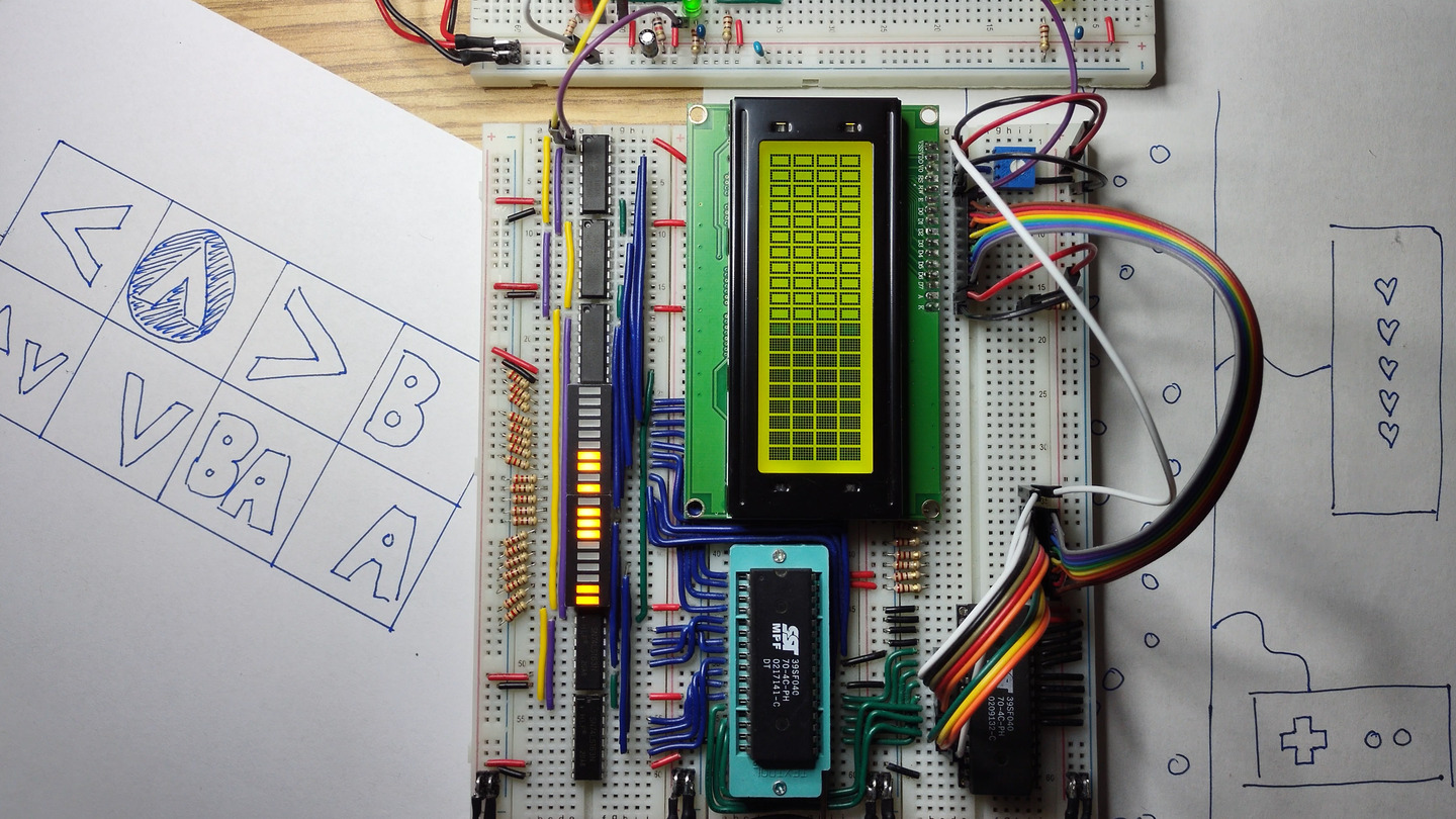
Homebrew CPU Plan Step 1
This video introduces the first milestone for our homebrew CPU project.
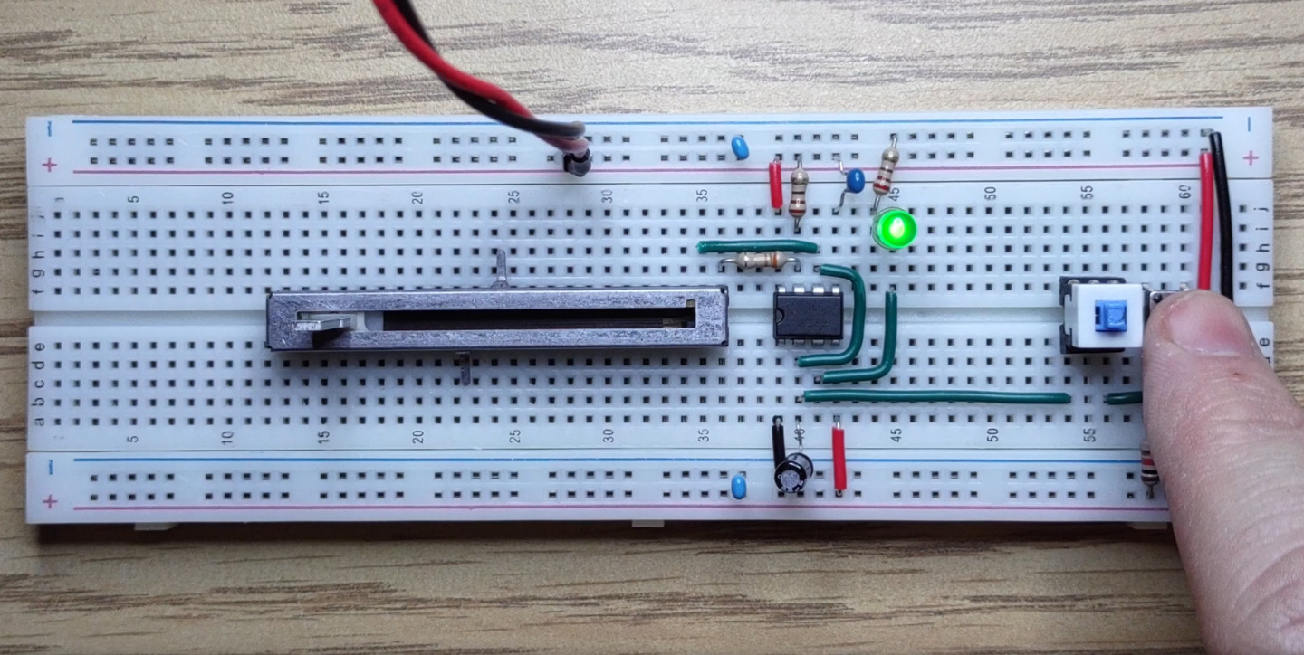
Simple Clock Circuit with a 555 Timer
In this video we create a clock circuit with a 555 timer in astable mode, and use it to blink a green LED.
Manual Clock Circuit Controls
We add a potentiometer and a single-step button to our clock circuit.
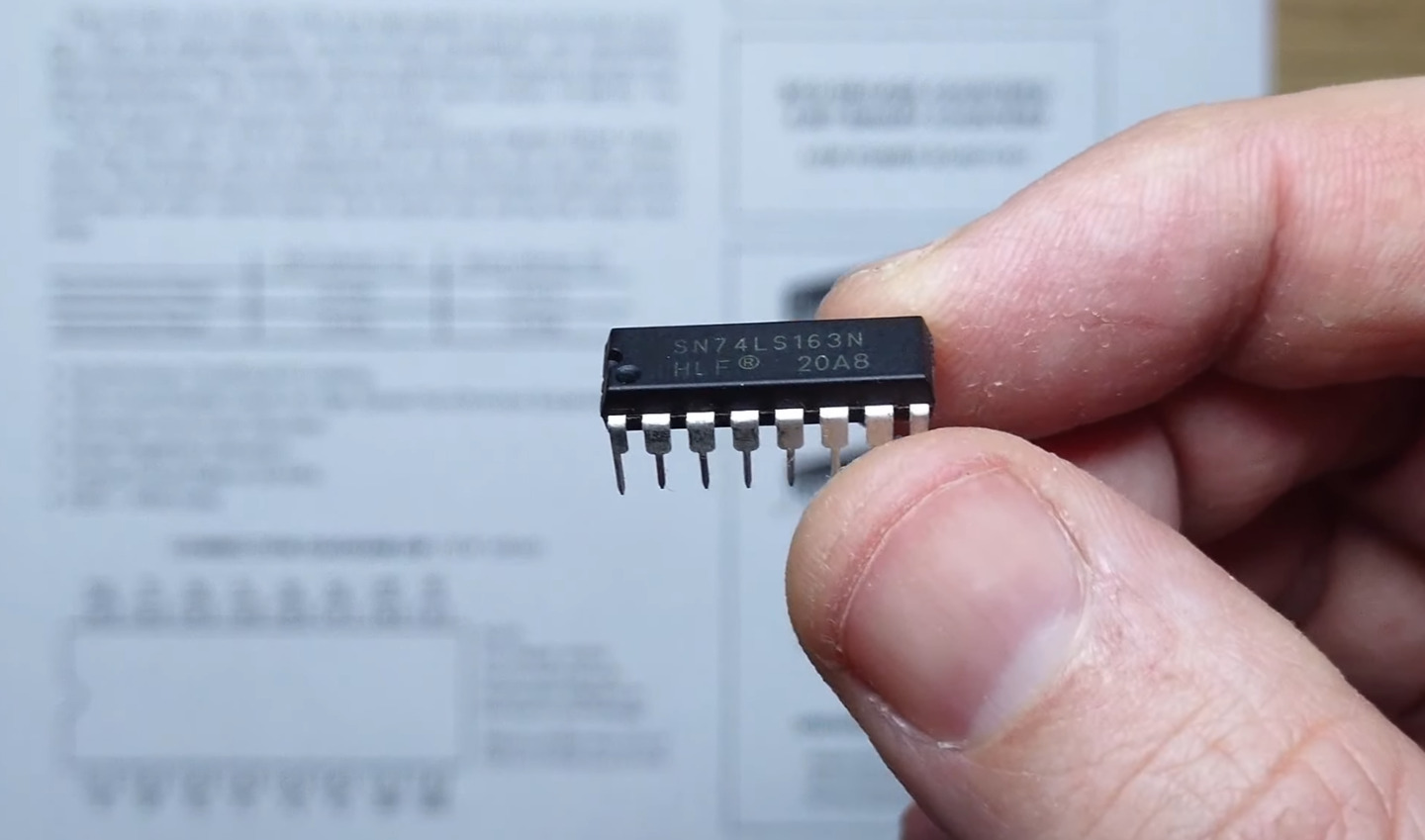
Synchronous 4-bit Binary Counter 74LS163
We connect our clock circuit to a 74LS163 synchronous binary counter and see how to count, reset and load values into the counter.
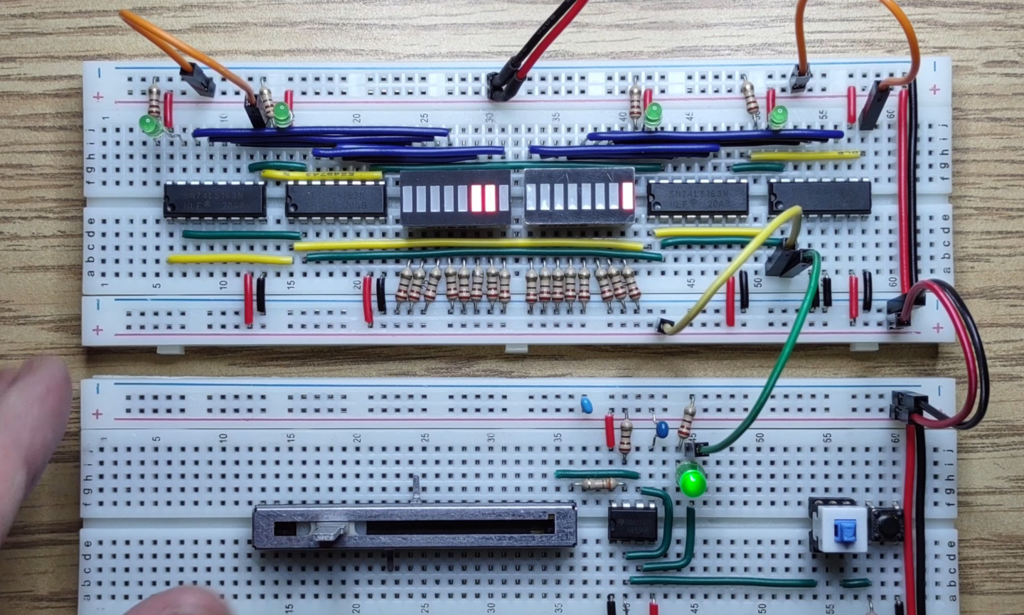
16-bit Address Register
We add three more 74LS163’s to our counter to make a 16-bit address register for our homebrew CPU project.
Power-on and Manual Reset Circuit
We add a reset circuit to our clock module that resets our address register to “0” on power-on and when a button is pressed.
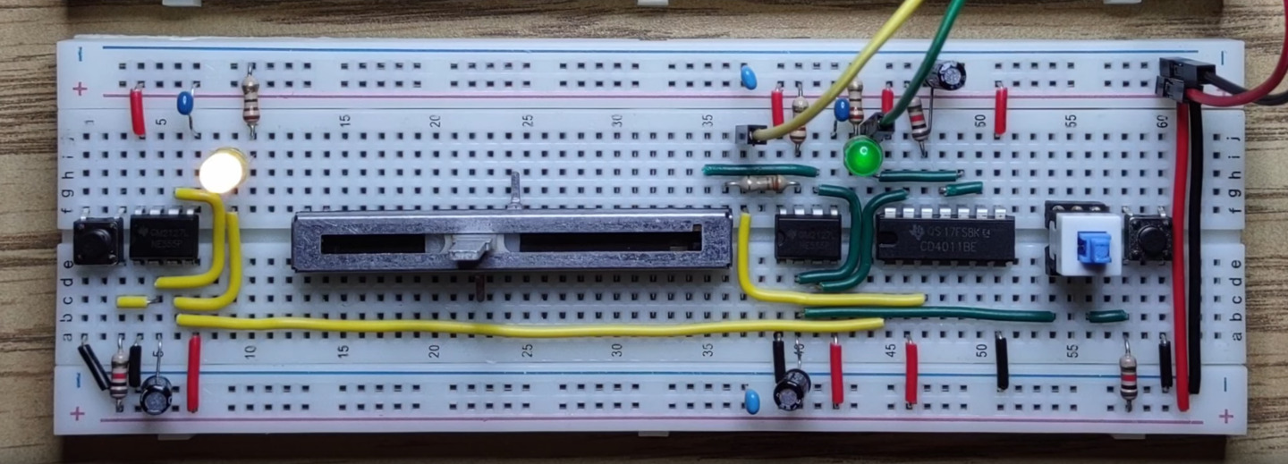
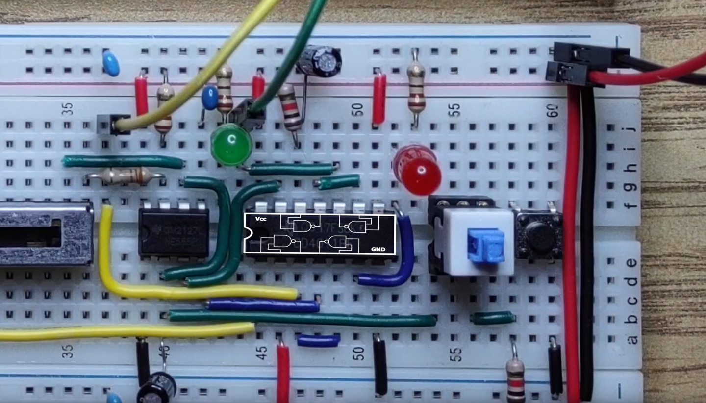
Clock Halt Circuit with 4011 NAND Gate and 555 Timer
We complete our clock module by adding a halt signal and test it with our address register. Now our (future) programs won’t have to run forever.
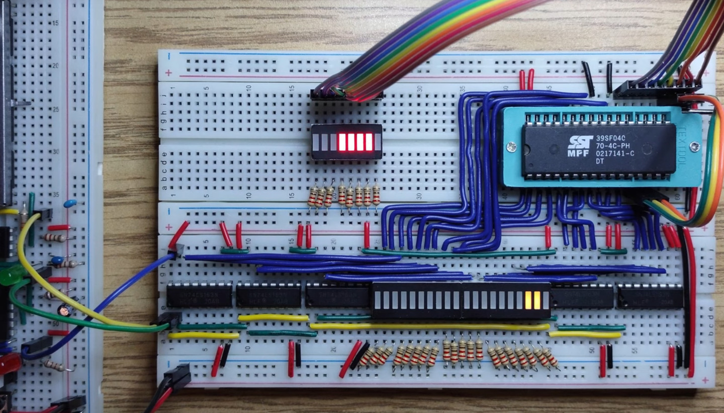
SST39SF040 512k Flash Upgrade
We build a larger address register and use it to test an SST39SF040 512k flash chip.
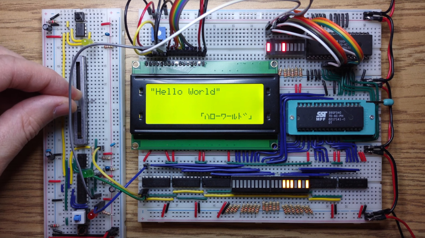
Milestone 1: LCD Character Display
We connect an HD44780-powered LCD character display to the circuit and play a simple text animation from the program ROM.
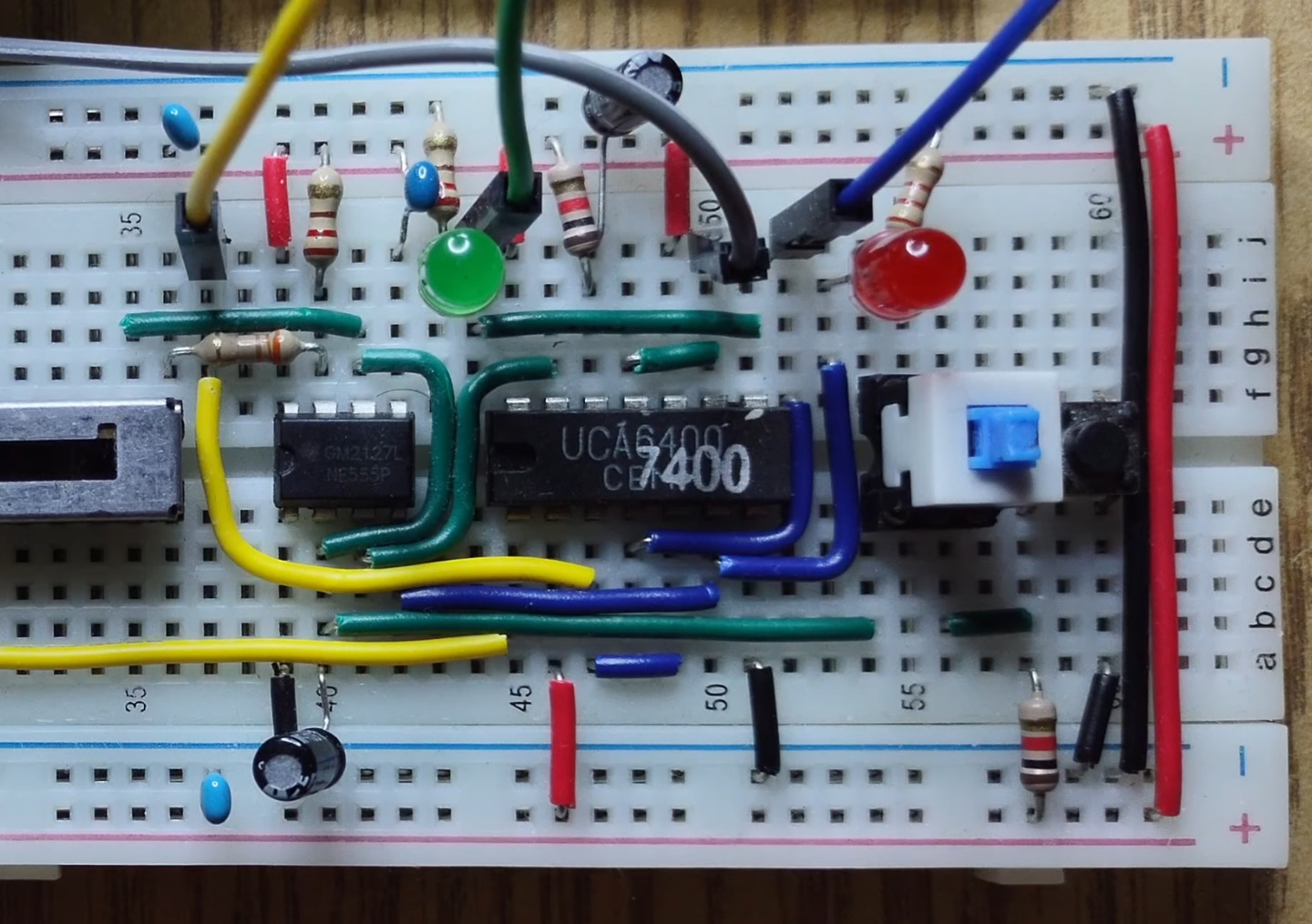
CMOS vs TTL: What are logic families?
In this video we replace our clock’s 4011 CMOS Quad-NAND gate IC with a TTL equivalent and discuss compatibility between different logic families.
Homebrew CPU Step 2: Rhythm Game Plan
We’re turning a movie-playing circuit into an actual interactive game. This video lays out what we need to do:
- Use the HD44780 scrolling feature for the play field
- Design custom CGRAM characters
- Build a controller for user input
- Build a health tracker to halt the circuit on game over
- Tie it all together with new logic, opcodes and program code


