We add a potentiometer and a single-step button to our clock circuit.
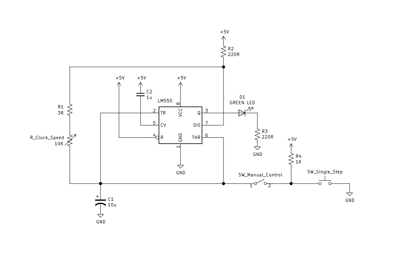
Schematic:
Transcript:
In the last video we built a simple clock circuit with a 10k resistor and a 10 microfarad capacitor.
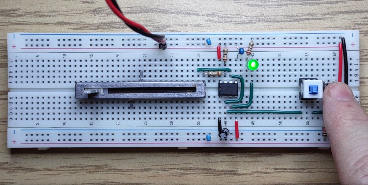
To make the clock rate adjustable all we need to do is replace the 10k resistor with a potentiometer.
We could use a normal potentiometer but this one is from a mixing board and operates on a logarithmic scale instead of linear.
Logarithmic scales are great for perceptual things like the speed of a blinking light, volume controls and brightness levels.
Logarithmic pots also guaranteed to be at least 2.718 times cooler than linear pots.
Let’s connect things up with a 3.3 ohm resistor in series to ensure a minimum resistance.
Now we have control of the speed of our clock
Let’s add a single step function.
When we’re in single step mode we want the clock output to be controlled by a push button.
This switch will be used to connect or disconnect our push button directly to pin 2 on the 555 timer and the
positive side of our 10 microfarad capacitor.
The push button is pulled high with a 1k resistor. This is enough to prevent the 555 from entering charging mode regardless of the potentiometer setting. When the button is pushed we connect pin 2 to ground, immediately discharging the capacitor and forcing the 555 into charging mode.
By connecting the button this way we get a debouncing effect without any extra components, because the capacitor will smooth the voltage change and the comparators in the 555 timer deliver clean edges on the output. This clock circuit is complete enough for us to start building a counter to be used as an address register.
We’ll build that in the next video.
I hope you enjoyed this one. See you next time.