We’re turning a movie-playing circuit into an actual interactive game. This video lays out what we need to do:
- Use the HD44780 scrolling feature for the play field
- Design custom CGRAM characters
- Build a controller for user input
- Build a health tracker to halt the circuit on game over
- Tie it all together with new logic, opcodes and program code
Transcript:
I make videos about basic electronics and we’re building a homebrew CPU that can play some simple games.
In earlier videos we built a clock and address register connected to a program ROM, a lookup table and a character LCD display.
This circuit can play movies from the program ROM.
We can control the speed of playback, single step and reset with the clock but there’s no other way to interact with it.
In the next few videos we’ll add user input and output to the circuit, letting us build the first real game.
One of the features of our character LCD display lets us scroll the screen contents left or right.
Let’s use that to make the play field for a basic rhythm game.
Rhythm games show symbols you need to press often moving from the top to the bottom if we turn the screen 90° clockwise we can draw our symbols sideways and scroll them right on the screen to move them down towards the player.
When symbols reach the edge of the screen you must press the matching button in time.
We could end the game on the first missed symbol
but it would be more fun to have a health bar so each time you miss pressing a button you lose some health and the game ends only when your health reaches zero.
Here’s what we need to build:
a health counter and display with logic so that it counts on every miss and stops the clock when it reaches zero;
a controller for user input that is synchronized to our clock;
a program for the program ROM that scrolls symbols across the character LCD display, this needs some special instructions for checking user input as symbols reach the edge of the screen.
Let’s start with the controller for user input.
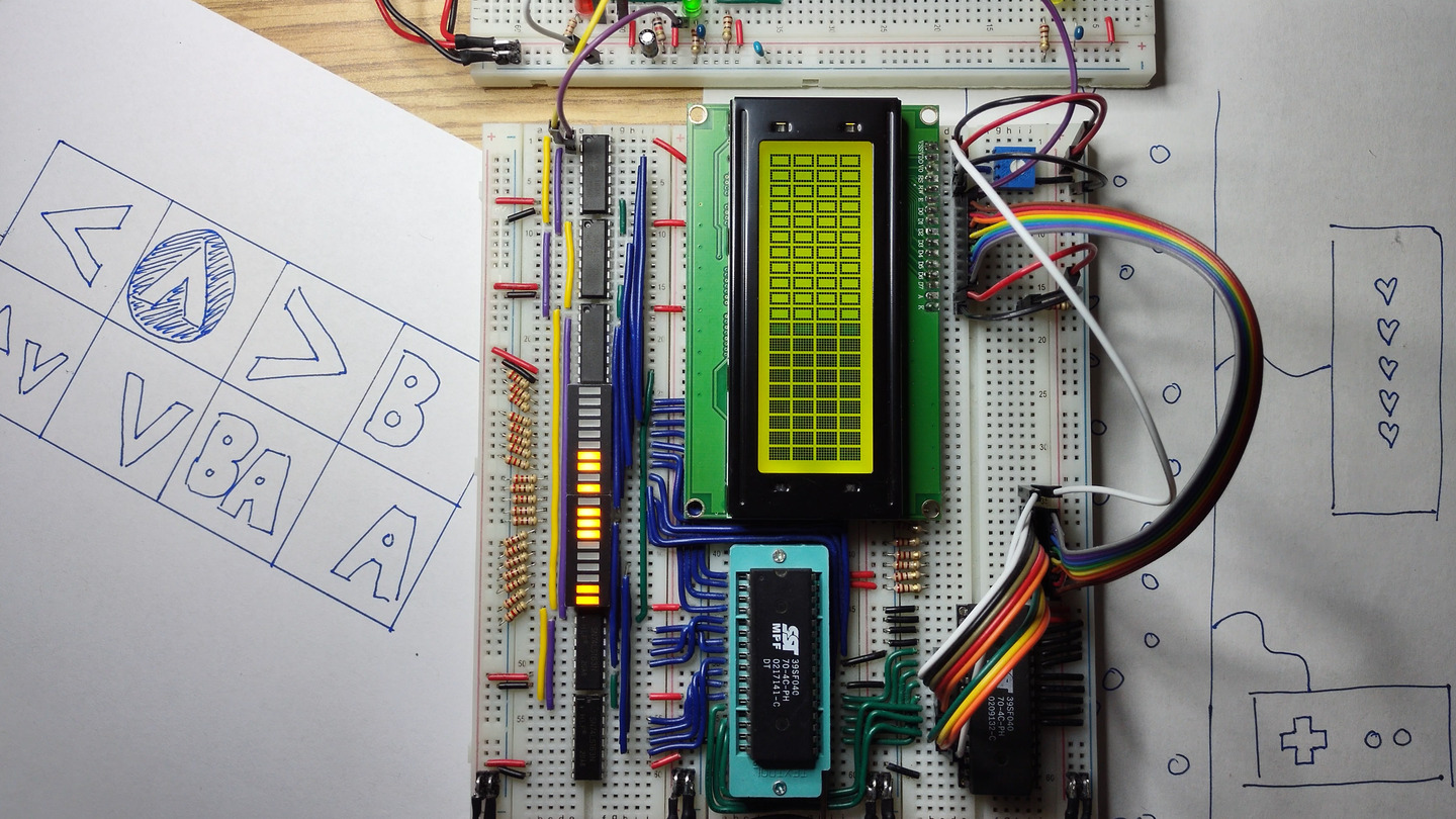
A direction pad with up, down, left, right and two buttons: B and A, is enough to start.
This is similar to the classic Nintendo Entertainment System controllers, for those of you old enough to remember it.
Four directions and two buttons makes six different inputs, so let’s draw a symbol for each one. Our character LCD will be rotated so where normally we have 4 rows of 20 5x8 pixel characters now we have 20 rows of 4 8x5 pixel characters.
Six symbols but four characters per row means some symbols will have to share columns.
Let’s have up and down share the second column and B and A share the last column.
Our character LCD display has eight CGRAM characters, characters for which we get to choose the pixel pattern.
We need one CGRAM character for each symbol:
Up, down, left, right, B, A. With up and down in the same column let’s make them look different so it’s easy to tell them apart.
And one for when both symbols are shown in a shared column: up and down at the same time and B and a at the same time. Six symbols plus two shared is eight so we’ve got just enough CGRAM characters.
In the next videos we’ll see how to design these pixel patterns, load them into CGRAM, display them on the screen, build a health bar, build a controller for user input, design logic connecting them and the whole rhythm game program.
Thank you for following along. If you like this video, like the video!
I’ll see you in the next one.