In this video we create a clock circuit with a 555 timer in astable mode, and use it to blink a green LED.
Transcript:
In this video we’ll build a simple clock circuit using a 555 timer.
I promise I’ll make at least one mistake so stay tuned for that.
The 555 timer has a flip-flop, a voltage divider and two comparators.
The voltage divider creates a reference level at one-third and two-thirds of our five-volt supply.
The flip-flop acts as one bit of memory that stores whether we’re charging or discharging a capacitor.
The comparators monitor the voltage of the capacitor to switch between charging and discharging modes.
When powered on the 555 will start charging the capacitor until it reaches the two-thirds point,
then the first comparator will toggle the flip-flop to discharge mode.
The capacitor will then discharge to the one-third point where the second comparator will toggle the flip-flop again and the process repeats.
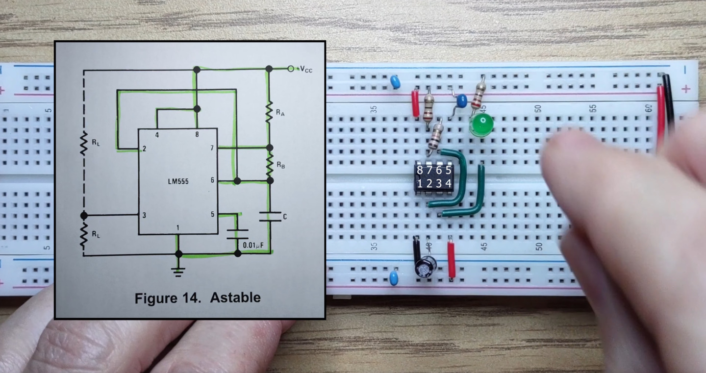
At the same time the output pin will give us the state of the flip-flop. While charging the output is high and while discharging the output is low. We’ll connect an LED to the output and we should see it blinking on and off. Let’s follow the astable wiring from the datasheet. First the 555 timer.
We’ll connect Vcc and ground,
and remember to connect the power rails.
We’ll connect pin 2 to pin 6 to enable astable operation.
We’ll add a 10 microfarad capacitor between pin 2 and ground.
We’ll add a 220 ohm resistor between pin 7 and Vcc.
Pin 4 is the enable pin. We’ll connect it to Vcc for always enabled.
We’ll connect an LED to the output now with a 220 ohm current limiting resistor.
We’ll connect the recommended decoupling capacitor from pin 5 to ground and add some decoupling capacitors to our power rails. These capacitors reduce the effects of rapid switching on the 555 timer. We’ll add a 10k resistor between pins 6 and 7. Our main capacitor is charged and discharged through this resistor so choosing a large value here will make sure that the output toggles on and off slowly enough that we can see it. Finally let’s connect the power,
and behold the blinkenlight,
the humble beginnings of our project.
In the next video we’ll see how to make the clock rate adjustable and add a manual control mode.
I hope you enjoyed this video. See you next time.