We add three more 74LS163’s to our counter to make a 16-bit address register for our homebrew CPU project.
Transcript:
We’re building a homebrew CPU, and in the last video we built a 4-bit counter as the start of an address register using a 74LS163.
However, the EEPROM we’re planning to use has 15 address lines,
So we’re going to need more bits.
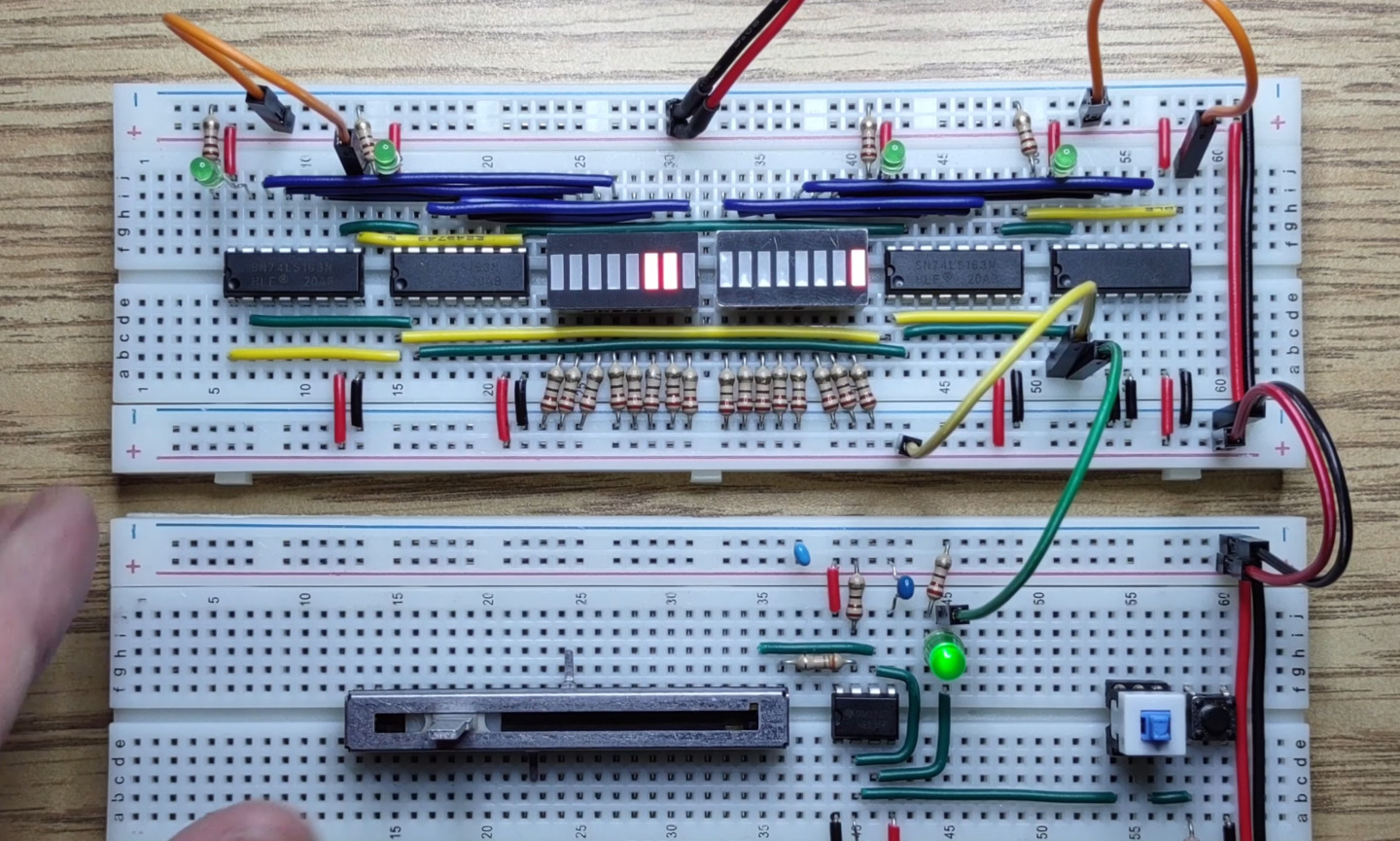
We will expand the counter by connecting three more 74LS163 chips to give us a 16 bit address register.
This series assumes familiarity with basic electronics.
If you’re looking for a place to get started please check the description below.
Let’s start by making room for more output connections
We add a second 74LS163 and connect almost everything the same as the first. Vcc to 5 volts.
Ground to 0 volts. Count enable parallel high, but count enable trickle will be connected to terminal count from the first 74LS163.
This is the same signal shown by the green LED.
This will prevent the second 74LS163 from counting on the clock signal unless all of the following bits are “1”.
For inverse parallel enable, inverse reset and the clock pin
we’ll connect across to the first 74LS163 so they apply at the same time.
We add an LED to show the terminal count and connect the output pins to our LED bar graph.
And here’s an 8-bit counter working just as we expect.
Every time all the low four bits are “1”s the next four bits increment when the terminal count is set.
Look at the terminal count on the new 74LS163. Notice that it doesn’t go high unless all 8 bits are high. That’s because terminal count also requires count enable trickle to be high. This lets us chain as many of these counters as we like by connecting terminal count from one to count enable trickle of the next.
With both inverse parallel enable pins connected together let’s bring them low.
All “1”s are loaded except for the two input bits we brought low.
With both inverse reset pins connected together let’s bring them low to see that we can reset our whole counter to all “0”s.
Now we can repeat the same process for the high eight bits of our counter
Two 74LS163s. Vcc to 5 volts. Ground to 0 volts. Count enable parallel high.
We’ll connect inverse reset and the clock pins.
Terminal count from the second 74LS163 to count enable trickle on the third.
Terminal count on the third to count enable trickle on the fourth, and let’s bring our output pins over.
Add a second LED bar graph
We’ll add LEDs for the third terminal count,
and the fourth.
And we’ll connect inverse parallel load to high for now.
let’s see if it works.
If we set the eight high bits to all “1”s with inverse parallel enable we can see the terminal count carrying through.
If we bring inverse reset low we can set all 16 bits to “0”.
This counter is now almost good enough to use as an address register for our EEPROM.
In the next video we’ll build a reset feature for our clock module so the address always starts counting from zero.
We’ll also need some halting logic so that the counter doesn’t run forever like it does now.
That’s the end of this video. See you next time.