We add a reset circuit to our clock module that resets our address register to “0” on power-on and when a button is pressed.
Transcript:
We’re building a homebrew CPU.
The first step of our plan is to build a circuit that can write instructions from an EEPROM to our LCD display module.
We’ve built a clock and an address register so far. Together they can count through all the EEPROM addresses.
We have a problem, though. When we turn on the power our address register starts from some random value and resetting it requires connecting the reset pins to ground.
That’s inconvenient.
Let’s build a reset circuit that will ensure our counter starts from zero and gives us a button so we can easily reset any time we want.
This video assumes familiarity with basic electronics including some timing diagrams and digital logic.
There are links in the description below if you’d like to brush up on these topics first.
The clock circuit we built has a manual mode that we can use for single stepping. Notice what happens when we’re in manual mode: when we connect the power it looks like we get a single clock pulse, or the clock output is high, immediately after connecting power.
This is what that looks like on a timing diagram. The clock goes high for a short time then drops low and stays low. We could use a circuit like this for a reset pulse because we want to reset our address at power on and then let the count continue afterwards.
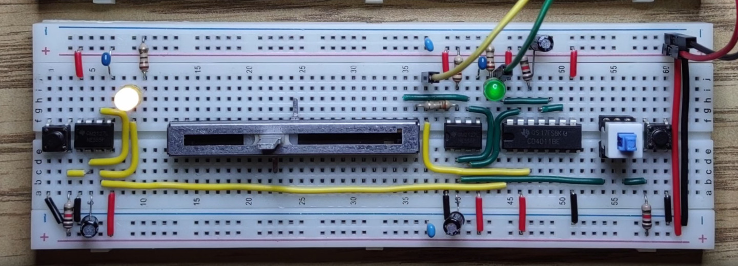
Let’s build a second 555 circuit for reset but this one will only operate in manual mode.
First a 555 timer.
A reset button on the left.
5 volts to Vcc.
0 volts to ground.
A decoupling capacitor.
Pin 2 to pin 6.
Connect our button to pin two.
This button will be pulled high with a 1k resistor,
and when the button is pressed it will go low.
Add a 10 microfarad capacitor from pin 2 to 5 volts.
Pin 4 high for “always enabled”.
And connect the output to a yellow LED
Now we have a reset line that goes high on power on and when we press the reset button.
Next we need to connect this to our address register’s inverse reset.
Inverse reset goes low when we want to reset and high when we want the clock to run.
An inverter will give us the output we need so we could use a hex inverter to invert the reset line,
or we could not do that.
We’re not going to have six signals to invert so instead let’s use a 4011 quad NAND gate
A NAND gate is called a universal gate. It can be used to build all the other logic gates. It’s very easy to turn a NAND gate into an inverter. One way is to tie one input high then we see that the remaining part of the logic table is the same: output is the inverse of the input.
Let’s move the clock output and green LED over a bit to make room for the 4011.
5 volts to Vcc.
0 volts to ground.
We’ll take the reset output over to one NAND input,
and set the other input high.
The output will be our inverted reset signal that we can connect to the address register.
Now let’s reset the counter by holding reset high and triggering a clock pulse.
The clock isn’t working, maybe a loose connection at the single step switch.
Yes, that’s working now.
We can count and reset the counter manually.
Let’s try powering on again.
We’re not resetting on power on yet.
What could be going wrong?
Looking at the data sheet for our 74LS163 counter
we see it says all changes, including reset, happen on the rising edge of the clock.
So what could be happening is the initial clock rising edge comes before the reset line goes high, or the clock line starts high so there’s no initial rising edge. Either way if we can delay the clock line going high a bit we should solve the problem.
We can delay the clock by logically ANDing it with an inverse pulse. Fortunately a pulse like this at power on can be
created with a capacitor to 0 volts and a resistor to 5 volts.
It will actually look more like this but from a logic point of view at some time it will be considered as changing from low to high.
That’s our inverse pulse.
What about ANDing it with our clock?
This is where our unused NAND gates come in.
A NAND gate is an inverted AND gate so if we invert the output we’ll have a normal AND gate.
Let’s build it.
First connect the clock output to one input.
Connect both a 10 microfarad capacitor to zero volts and a 1k resistor to 5 volts to the other input.
Connect the output from the first NAND gate to one input from the second.
Connect the other input to 5 volts and the output from the second NAND gate is our new clock.
Power on.
Here we go.
Both reset and clock are coming on now and Our clock is starting from zero every time
In single step mode it works too
We’ve built a reset circuit in this video.
I hope you enjoyed it.
in the next video we’ll add the ability to halt the clock automatically.
See you next time.