We connect our clock circuit to a 74LS163 synchronous binary counter and see how to count, reset and load values into the counter.
Transcript:
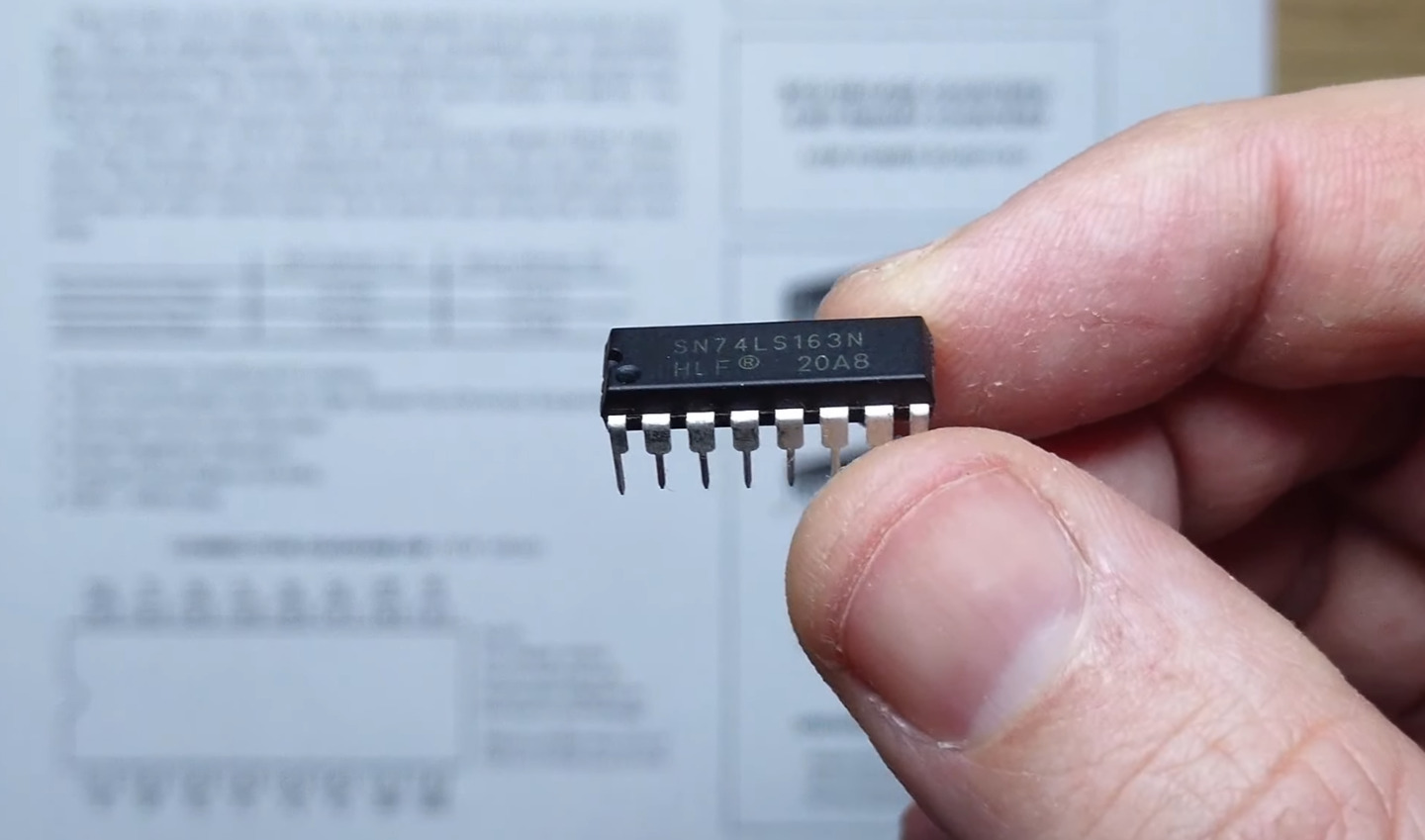
Let’s look at the 74LS163 synchronous binary counter and see how to count, reset and store values with it.
We’ll use our clock module to drive the clock input.
Q0 through Q3 output the 4-bit counter value and the terminal count will be useful so let’s connect an LED to that as well.
When the count mode is enabled this binary counter works by flipping the least significant bit, Q0, on every rising edge of the clock. Q1 is flipped on every falling edge of Q0, Q2 is flipped on every falling edge of Q1 and Q3 is flipped on every falling edge of Q2.
We can see all 16 states of the counter by adding the binary digits.
The terminal count output is high only on the last state before rolling back to zero, when all the bits are “1”.
Here’s the clock module we built and a new breadboard for our counter.
First connect our power rails. Let’s see if the clock is working.
Looking good. Now the 74LS163.
5 volts to Vcc. 0 volts to ground. Count enable parallel high. Count enable trickle high. Inverse parallel enable high for now. Inverse reset high as well. We’ll connect our clock output to the clock pin. Now we’ll use an LED bar graph for Q0 through Q3 with 220 ohm current-limiting resistors.
Q0, our least significant bit, is on the left. Let’s put it on the right of the bar graph. Next we connect Q1, Q2 and Q3
For terminal count we’ll use a green LED.
Let’s turn it on.
We’ll slow down the clock and we can see the binary count on the LED bar graph.
The terminal count LED blinks on when all the counter bits are on.
We’ll use single step to advance one state at a time.
We can see terminal count again.
Let’s see what happens if we bring inverse parallel enable low.
When we advance the clock all bits are set to 1, this is because we left the parallel inputs unconnected and on LS-series chips inputs are pulled high.
Let’s connect two of the inputs to ground and try again.
This is how we can store a value in the register.
With inverse parallel enable high again counting continues as normal.
With inverse reset low all bits will be set to zero on a clock pulse.
In this video we’ve seen how to use a 74LS163 to count, reset and store values.
In the next video we’ll expand this 4-bit counter to a 16-bit counter.
See you next time.