We connect an HD44780-powered LCD character display to the circuit and play a simple text animation from the program ROM.
Transcript:
In this series we’re building a homebrew CPU just capable of playing some simple games. In the last video we connected our clock module to a 20 bit address register and used it to read values from a 512k flash chip.
Let’s take a look at the datasheet for the HD44780 controller on the LCD character display. We can send commands with the eight data pins and one register select pin. The RW pin can be used to read back data, including the status as to whether a command is completed. But all commands complete in 1.52 milliseconds so as long as our clock stays below 650 hertz, we don’t need to connect that pin for now. This means we need to control nine pins plus clock to send commands, but our program ROM has only eight bits of output data. The HD44780 does have a 4-bit mode we could use to solve this problem, but instead let’s see how we can create 9 control bits from our 8-bit program data.
The commands we can send when RS is low are divided up based on the number of leading zeros. We’ll use Function Set, Display Control, Entry Mode Set and Clear Display to initialize the screen so we can start drawing characters.
When RS is high the data value selects characters to display on the screen based on the character ROM.
We can arrange the commands available when RS is low into a grid as well, and choose names for the separate commands.
INI for initializing the display to 8-bit mode. CUR for enabling the display and underline cursor.
EIN for incrementing cursor and no display shift. CLR to clear the screen.
To combine these tables so we can send both commands and characters with only eight bits, we’re stepping into the third dimension. The holes in this sheet mark where we want to set RS low for sending commands. To make this happen we can program a second ROM with a lookup table of values for RS, based on the 8-bit program ROM value. The program ROM value is passed through the 8 data pins on the character display to complete the input.
Let’s build the circuit. First remove our old program data display.
Next add a new breadboard for the lookup table. We’ll use another SST39SF040 flash chip. This chip is much larger than we need for a 256 byte lookup table, but in future videos we’ll make use of the extra capacity. As mentioned in the last video it’s really easy to accidentally bend the pins on a chip like this, so the last time we used a ZIF socket. This time let’s put the SST39SF040 in a socket header. A socket header has rigid pins that are much less likely to bend when inserting into the breadboard. Just make sure to use a header with round holes because the square holed ones are only good for soldering to a circuit board.
We connect program data to the low address bits and all other address bits to ground.
The low data bit from the lookup table will contain the value for RS.
Let’s connect a new LED bar graph so we can see the RS value and the program data value.
We start the clock in single step mode.
The first program data byte is 0011 1011 and the RS value is low which will send the INI command setting the display to eight bit mode. The second byte is 0000 1110 and the RS value is low which will send the CUR command enabling the display and showing the underlying cursor. The third command is 0000 0110 which enables incrementing cursor and no shifting. The fourth command is 0000 0001 which clears the screen. The fifth command is 0010 0010 and the RS value is high which will send a double quote character to the display. This looks good! Let’s connect the display and see if the program works.
VSS to 0 volts. VDD to 5 volts.
V0 through a 5k potentiometer to 0 volts, to control contrast.
RS or register select to the lookup table output.
RW or read/write to 0 volts. We’re only writing data for now.
Enable to the inverse of our clock signal, so that on the rising edge of the clock we advance the address register, and on the falling edge we send a command after it stabilizes.
D0 through D7 are connected to the program ROM
A to 5 volts and K to 0 volts. These are power for the backlight.
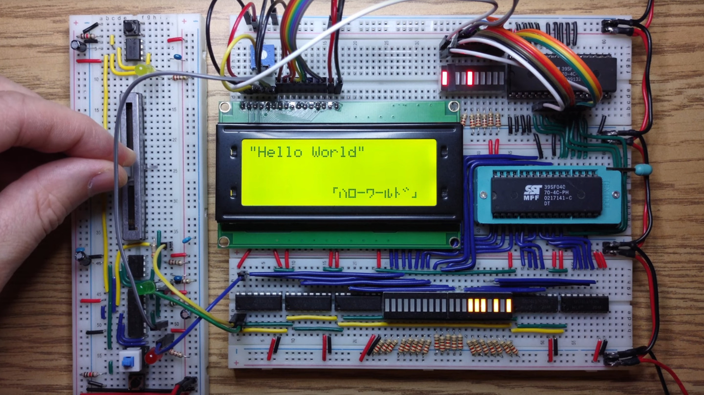
With the LCD character display on here now we’re having some power distribution issues. Let’s replace the jumper wires we have on here with something a little more solid. These two by two headers have connections soldered from one to the next that should work a lot better. Let’s start the clock in single step mode to test our program. We initialize the interface. We show the underline cursor. We set the entry mode, and we clear the screen.
Then start drawing “hello world”. The character display memory is interlaced so line 1 is drawn followed by line 3, then line 2 and line 4. We have some katakana characters so this is hello world in Japanese too.
The rest of the program redraws the screen with small changes to the background and moves the text diagonally back and forth.
In this video we completed our first milestone of building a circuit that can display simple animation on an LCD character display. There’s more to build to reach the ultimate goal of using this circuit to play some simple games, and we’ve only just scratched the surface of what this display module can do.
We’ll explore those features and continue the build in the next videos. Thank you for watching. See you next time.