This is part one of a two-part series. Read part two here.
This post covers how we interface a 32K EEPROM, a clock and an address register to a 20 x 4 LCD character display module and use it to play a video. We “decompress” the video by expanding our 8-bit data stream to 9 bits for playback in hardware. There is no CPU or microcontroller involved.
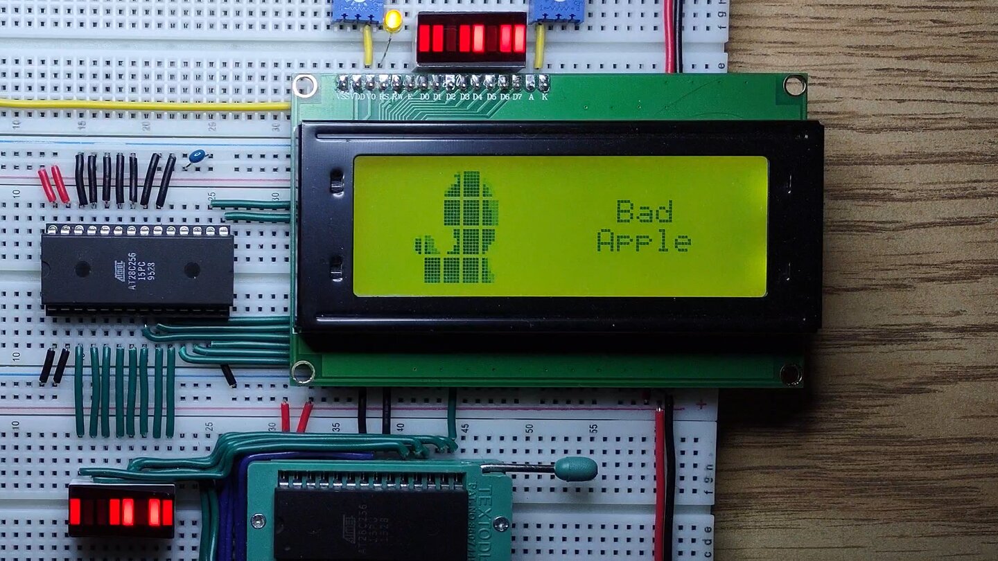
To test step 1 of the homebrew cpu project we’ll see if we can play an actual video from the EEPROM to the LCD character display module. Bad Apple is an ideal video for this purpose: it’s essentially monochrome and most of the video is recognizable even at a very low resolution.

The original Bad Apple video has 6569 frames at 30 fps for a running time of 3m39s. We have 32768 bytes so we need to run our clock at 150 Hz to fit the complete video in EEPROM.
This gives us about 5 bytes of data per frame of video, or a constant video bitrate of 1.2 kb/s.
LCD display memory
The LCD character display module uses an HD44780 controller and has 20 columns of characters and 4 rows of character cells. Each character cell is a 5 x 8 grid of pixels with a single pixel space in between.

The memory used to display characters is split into two banks of 80 bytes each. The banks are interlaced so that bank 1 (D00-D39) covers lines 1 and 3, and bank 2 (E00-E39) covers lines 2 and 4.
Our video area includes addresses 00-07 and 20-27 in both banks.
Bad Apple has a 4:3 aspect ratio which maps nicely to the 40 x 32 total pixels in our video area of 8 columns and 4 rows.
Character ROM

The character ROM on the LCD display module includes a “space”
character with none of the pixels set and a solid block character
('\xff') with all pixels set. These can be used to quickly paint
the solid parts of the video area.
CGRAM
Custom character patterns are made possible with CGRAM. We have 8 CGRAM characters (CG0-CG7):

The pixel patterns are given by the low 5 bits stored at each CGRAM address. CGRAM is contiguous but we number the addresses based on the character and row. E.g. C10 is the first row of CG1, and follows immediately after C07.
With only 8 CGRAM characters at least 75% of our video area character cells need to be blank or a solid block. We’ll have to be clever about prioritizing use of CGRAM character cells to make it seem like the whole video area is a bitmap.
LCD commands
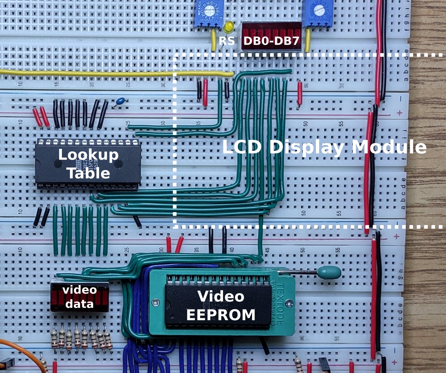
We interface with the LCD display module using 8 data pins (DB0-DB7) and a register select (RS) pin.

When RS is low we can set the display memory (DDRAM) or CGRAM address, clear the screen or issue other cursor and display commands. When RS is high we can write character data to display memory (DDRAM) or send pixel data into CGRAM.
This code table can be expanded into a grid like the character ROM grid above:

We can see there are some unused values, like most of the function set range and part of the set DDRAM address range. There are also some commands with duplicate values like cursor or display shift commands and return home.
Command compression
The EEPROM can only output 8 bits at a time but we need 9 bits including RS to fully control the LCD display module.
If we add a 256-byte lookup table for RS then we can combine sending character codes and LCD commands into 8 bits. Also if we reassign the upper 4 bits (DB4-DB7) we can assign new positions for commands in the table.
This is how the lookup table is wired to RS and the upper 4 bits (DB4-DB7):
In the table reassigning the upper 4 bits is the same as moving a command left or right. This lets us fill in unused values or repeated commands, move the set CGRAM address and function set commands out of the way, and replace unneeded commands.
Command lookup table
This is the combined lookup table that we use to map 8 input bits from the EEPROM to 9 output bits for the LCD display module:

lookup_table.py is the Python version of the same table:
# byte order from top->bottom, left->right
# (mnemonic:)hex-value
hex_map = """
C00:04 C20:05 12 13 14 15 16 17 D00:08 D16:09 D32:0a C40:06 E00:0c E16:0d E32:0e C60:07
CLR:00 C21:05 12 13 14 15 16 17 D01:08 D17:09 C01:04 C41:06 E01:0c E17:0d E33:0e C61:07
HOM:00 C22:05 12 13 14 15 16 17 D02:08 D18:09 C02:04 C42:06 E02:0c E18:0d E34:0e C62:07
  R:01 C23:05 12 13 14 15 16 17 D03:08 D19:09 C03:04 C43:06 E03:0c E19:0d E35:0e C63:07
...
The optional mnemonic labels a position and the hex value is the value stored at that position in the table. The low 4 bits of the hex value are connected to the high data lines of the HD44780 controller and the next bit is connected to the RS line.
Let’s look at two examples:
The second position on the left “CLR:00” is offset 0x01 in order from top to bottom:
- has a mnemonic of
CLR - has a hex value of
0x00which means “set RS to0and DB4-DB7 to0b0000” - DB0-DB3 are copied from the low bits of the offset value
0b0001 - sending this command will clear the screen and reset the cursor position on the LCD display
The third position in the fifth column “14” is offset 0x42 in order from top to bottom:
- has no mnemonic but corresponds to ASCII character “
B” - has a hex value of
0x14which means “set RS to1and DB4-DB7 to0b0100” - DB0-DB3 are copied from the low bits of the offset value
0b0010 - sending this command will output a “
B” character and advance the cursor on the LCD display
All mnemonic offset values are exported from this table as simple variables in a Python module baconsts.py:
C00 = b"\x00"
CLR = b"\x01"
HOM = b"\x02"
R = b"\x03"
...
Ready for video encoding
This mapping allows issuing one command per clock cycle from our EEPROM to our LCD display module including:
- addressing all CGRAM
- addressing most of display memory (all of the video area)
- output ASCII(ish) characters and the solid block character
'\xff' - output CGRAM characters (CG0-CG7)
- initialize the display with function set (
INI) - set the entry mode to “increment, no shifting” (
EIN) - clear the screen (
CLR) - hide the cursor (
HID)
These are all we need to play our video and show text on the right side of the display.
👍 Thank you for reading this far. We covered the interface between our EEPROM and LCD character display module, and how we perform hardware decompression on the data stream.
In the next post we explore the software that encodes video onto the 32K EEPROM using these commands.