This youtube tutorial covers interfacing with an LCD2004 20x4 LCD Character Display module with an HD44780 controller using only switches and simple components on a breadboard.
- 0:00 Introduction
- 0:21 LCD2004 available options
- 1:21 Power, contrast and back light
- 2:29 Control lines
- 6:02 Initialization
- 7:41 Writing to the screen
- 8:58 Enable line debouncing
- 10:51 Cursor positioning, interlaced memory layout
- 17:27 Reading data
- 20:04 CGRAM custom characters
- 21:05 Shifting the display left/right
- 22:11 Ending: Space Invaders playfield
Transcript:
Let’s look at the LCD2004 LCD character display module powered by an HD44780 we’ll see how to set the contrast and brightness then we’ll cover all the control pins, initialization, writing to the display, cursor positioning, reading from the display, creating custom characters, and shifting left and right.
This is an inexpensive display module that’s quite easy to find.
I bought this for about ten dollars from an Amazon seller.
It’s typically shipped with an SPI adapter like this one, and it’s up to us to solder this onto the module.
This is very useful if you’re working with a microcontroller but we’re not going to be using a microcontroller today so instead I’ve soldered a row of header pins on so that this display module can be plugged directly into a breadboard for testing.
When buying an HD44780-powered display check to see which character ROM it ships with.
Most of the characters in the first half will be the same, these are mostly ASCII characters but the second half of the characters can be wildly different from one model to the next.
Interestingly the HD44780 datasheet only mentions using the controller with a one or a two line display not a four line display like this one, so we’ll see what tricks this module uses to display four lines.
Let’s start by connecting the power.
VSS connects to zero volts.
VDD connects to 5 volts.
For v0 I’ll connect a potentiometer that lets me set the contrast.
There we have our test pattern.
For the backlight we use 5 volts to A and 0 volts to K.
This will give us the full brightness.
If we want to get a little bit fancier than that we can connect a potentiometer here as well.
Now i can set the brightness to any level that i like.
The next few pins are ones that we can find described on the datasheet.
First we’re going to connect register select which lets us choose between the instruction register or the data register.
I’d like register select to be normally 5 volts, normally high.
So I’m going to connect through to high on the other side of this button, and when the button is pressed we’ll go to zero volts.
So that we can see what the state is we’ll add an LED.
next I’ll connect the read/write pin and I’ll set it low for now.
In order to issue any command I need to use the enable pin so I’ll connect that one to a button now.
This is one that i want normally low, and I’ll connect an LED to this as well.
I’m going to need some more room for the data pins D0 through D7.
I’m just going to pop off the display module and one thing to notice is that the ordering of these is the reverse of what I would normally have.
The D0 is the least significant bit so it’d be nice to have that on the right side so let’s just reverse these.
I’ll connect these lines to an LED array, and let’s use some dip switches to control these values for input.
When the switch is closed these will be connected to 5 volts, and when the switches are open we’ll pull them down to zero volts.
Let’s see if we’ve got this working.
Power on.
Our register select is showing high, when I press it it goes low, that’s perfect.
Our enable line is low, when i press it goes high, great.
My dip switches all seem to be working.
The first command to issue is a function set to set the interface display length and number of lines so the display length will be set to one, sorry, the data length will be set to one, which means that we’re going to be using eight bit sequences instead of four bit sequences and the display lines will be set to one as well which means we have a two line display instead of a one line display. F will be ignored in our case for for a two line display.
I’ll need bits 11 1000 with register select low and enable.
Okay the screen seems to be cleared.
Next I want to use the display control on and off to enable the display and enable the cursor.
With the cursor I have the option of having an underline cursor or blinking or both, so just to test it out I’ll enable both of them.
This would be 1111, with register select clear.
Here we go so I seem to have a garbage character but I have my cursor there blinking.
Let’s see if I can clear the display.
The clear display command is just a single 1, register select low.
Okay I’ve just cleared the display and my cursor is blinking.
Next I’m going to try to write some characters.
I like this little confused face on the bottom line here.
In order to send this i need to send 0100 1111.
This time the register select will be high because I’m writing data.
The next character ends the same but has 0101 at the beginning.
And the next character ends the same but has 0110 at the beginning.
For the confused face let’s add a question mark, this will have 0011 at the beginning.
Oh.
So what just happened there?
In order to fix this, what’s actually happening is that we’re getting a bounce on the enable line and the display will trigger every time the enable goes from low to high but because this button isn’t perfect, sometimes when i press down I’ll get more than one click, like that.
So a simple way to fix this would be to add a capacitor and a couple resistors.
Okay that’s much better now.
While i was playing with the enable line a whole bunch of other characters came through.
Now what happens when the button is closed: the five volts is allowed to charge up this capacitor so that the the level goes from zero to five volts slowly and then when the button is open the capacitor discharges through these two resistors back to zero.
That should eliminate our bounce issue but notice something that’s funny going on here.
Our display is interlaced.
As I continued from the first line the next characters came in the third line, and after the third line it jumps back to the second line.
In before i forget: let me connect an LED back up to this so that I can see what’s going on.
There we go, perfect.
So let’s look at this display and see if we can figure out what’s going on with the memory addresses.
On the datasheet here when we’re looking at the way the memory addresses work for a 16 character by two-line display.
We can see that the addresses start at 00 and go through 0F. on the second line they start at 40 and go through to 4F.
Our display here is 20 characters wide so we have an extra four characters on here.
We can see that when the display is shifted left what happens is that the address of what’s displayed on our display would move over to the right, so the first position in the top left corner becomes 01 and the first position on the second line becomes 41.
When we’re shifting to the right the display goes to the left and the memory addresses that appear in the first position and second position are 27 hex and 67 hex respectively and these refer to the all the memory addresses that are available for the HD44780.
The way this maps to the lines that we have is the first and second lines come first and then the third and fourth lines come after that but in memory, they’re arranged like this.
So scrolling left and right or shifting left and right will move characters between the first line and the third line and characters between the second line and the fourth line depending on which direction we’re going, and all of the memory addresses from 00 all the way up to 27 are used so there’s nothing hidden there, everything is always displayed.
The same is true for all of the memory addresses from 40 up to 67 hex so let’s draw the rest of those out and see see where that puts us.
So we should be able to use this to move to any address that we’d like on the screen, where the third and fourth rows are here and the first and second rows are here.
We can set the cursor position by setting the high bit, and we’re sending to the instruction register so the high bit set and all zeros according to this should put us on the top row in the first character.
That worked.
If we want to go to the last character on the first row and we should be going to 13.
That worked.
If I want to go to the last character on the last row then this should be 4F.
Oh my mistake, I got confused, this is the second row.
If I want to go to the last character on the second row it would be 53.
There we go.
If I want to go to the last character on the last row it should be 67.
There we go, and if I want to go to the first character on the last row it should be here at 54.
Perfect.
I’ve been talking about shifting but let’s take a look at how this would actually work.
In the entry mode set command I can say that every time I enter a character, instead of moving the cursor or in addition to moving the cursor I’d like the the screen to shift in the opposite direction so let’s start with that.
First I’ll move up into the middle of the screen here, and I’ll type an H character, and again, and again.
So we can see that as I’m typing everything that’s on the third line is wrapping back up to the first line.
Everything is on the first line is coming back down to the third line.
Everything that’s on the second line is wrapping back down to the fourth line and everything on the fourth line is wrapping back onto the second line.
This is a very quick way to update the whole display if you’d like to move text over, we just need to take care to clear out the characters before we move them like this.
I’d like to reset the shifting.
We can use the return home command which resets the shift and sets us back to position zero.
Now we can see the memory layout as it as it was originally without any shifting applied.
Let’s look at reading data from the display module.
First we connect a switch to the read/write pin.
When this pin is high we’re asking the display module to set D0 through D7 pins high or low.
Now this is a problem, because our dip switches might be forcing one line high when the display module is trying to force it low, and if that happens we could have enough current running through to damage the display module.
To prevent damage we can use the second pole of the read/write switch to disconnect the high lines from all the dip switches.
Of course this is one more opportunity to add an LED so we can see the state of the read/write pin.
Okay this is what we want.
When the read/write pin is high, which means read, we don’t want any of the dip switches pushing any of the D0 through D7 lines high; but when read/write is off, when we’re in write mode, the dip switches operate as normal.
Okay let’s initialize the display module again.
This time I’ll just use the underline cursor instead of the underline and the blinking cursor.
I’ll use the control code 1 0 again to return home.
Now if I enable read mode and press the enable button then i should be able to read back the data that I entered here.
That’s the code for A, code for B, code for C, code for D, E, F, and that’s a blank space.
When we read from the instruction register we can also get the address of the cursor location as well as a busy signal.
So this is the address of the current cursor location.
You notice that the location doesn’t change when we do that read.
The top bit of this will indicate whether there’s an operation currently in progress and we’re not able to send additional commands.
With this particular setup on a breadboard it’s going to be basically impossible to ever activate the busy signal, but if you’re controlling this with a microcontroller it’s going to be very important to know that you’re not sending commands too quickly, especially for commands that take longer such as the clear screen.
Let’s look at CGRAM next.
If i put in characters 0 through 7 I should be able to display characters that i control the bitmap for.
This is character zero, one, two, three, four, five, six, and seven.
Next I use the command to set the CGRAM address to move my cursor where I’m going to be writing
data into CGRAM instead of into the DDRAM.
Writing to the data register lets us set the pixels for the CGRAM characters.
The low five bits are used to set one row of pixels and there are eight rows of pixels for each character.
Now that i have some space invaders let’s arrange them on the screen.
Now let’s animate these with the display shift.
This is a way that we can shift the display without adding a character to it.
With the instruction register set, 1 1000 should shift to the right… or to the left.
1 1100 should shift to the right.
There we go.
Shift back.
With cursor shift I can shift the cursor without needing to know the exact address of the character
that I’m moving to.
This will let me move one character to the left or one character to the right.
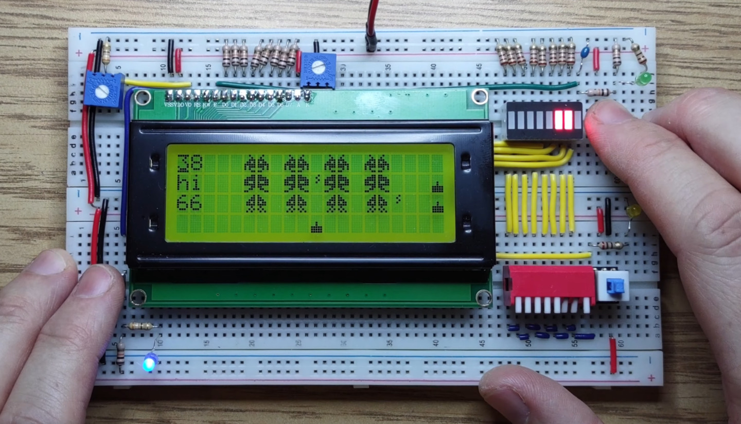
Let’s finish off our space invaders playfield with some enemy projectiles, a score display and a life counter.
Thank you for watching, I hope you enjoyed this video.
I’ll see you next time.